Laser cutting is becoming more precise, faster, and more adaptable in 2026. Yet heat remains a quiet threat. Excessive thermal energy can discolor edges, distort thin sheets, and weaken sensitive materials. These problems often appear after the cut, when correction becomes expensive.
This guide examines how to reduce heat damage in laser cutting processes through practical, controlled methods. It explores pulsed laser operation, optimized cutting speeds, suitable power settings, assist gases, and improved beam focus. Experienced operators know that one setting rarely fits every material. Stainless steel, aluminum, acrylic, and engineered composites respond differently under the same beam.
Small details matter. A clean lens can improve energy delivery. A sharp focal point can narrow the heat-affected zone. Shorter passes may protect delicate surfaces. Monitoring sparks, kerf width, and edge color also provides useful evidence during production. These observations support better decisions than relying on preset values alone.
The latest systems use sensors, adaptive controls, and software-based thermal monitoring. However, automation does not remove the need for judgment. Material batches can vary. Workshop temperature can change. Even a slight focus error may leave a rough, overheated edge.
There is no universal solution. That is worth remembering. The most reliable results come from testing, recording, and refining each parameter. This article presents proven approaches while acknowledging their limits. It also considers practical mistakes that can mislead operators, especially when a visually clean cut hides internal heat stress.
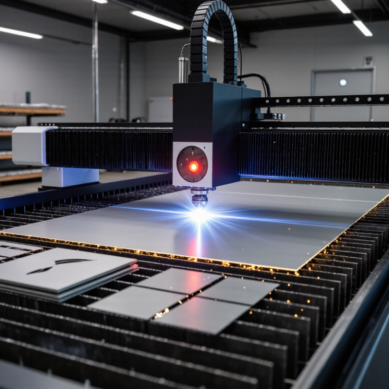
Laser cutting in 2026 still relies on a few core approaches: fusion cutting, flame cutting, and sublimation cutting. Each removes material differently. Fusion cutting melts the kerf and uses assist gas to eject it, while flame cutting adds an oxidation reaction. Sublimation turns material directly into vapor, often with pulsed energy and careful focus. The right method depends on material, thickness, edge quality, and production speed.
Heat control starts with matching power, travel speed, focus position, and assist-gas pressure to the sheet. Too much energy per millimeter widens the heat-affected zone and may discolor thin metal. Too little can leave dross or incomplete cuts. Small tests matter. A clean edge is not proof that the entire sheet stayed cool.
Operators can reduce heat buildup by using short lead-ins, spacing neighboring cuts, and alternating between distant areas rather than tracing one hot region repeatedly. Secure workholding helps keep the sheet flat, while a clean nozzle supports a stable gas jet. For delicate parts, lower peak power with pulsed output may limit thermal spread, though it can slow production. Material coatings, surface condition, and machine calibration also change results. Settings should be verified on a coupon from the same batch; published starting points may be close, but not exact. Heat still travels.
This chart compares representative wavelengths used by common laser sources. Wavelength alone does not determine heat damage: material, thickness, power, cutting speed, focus, assist gas, and pulse settings all matter. To limit heat input, optimize cutting speed and power, use an appropriate focus and assist gas, and consider pulsed operation when suitable.
Laser cutting does not damage material through heat alone. Damage depends on how the surface absorbs the wavelength, how quickly energy arrives, and how readily heat moves away. In metals, energy can spread into nearby material, leaving a wider heat-affected zone, discoloration, or slight edge-hardness changes. Reflective metals may absorb less energy initially, then respond sharply as the surface warms. That transition is easy to underestimate.
Wood and polymers behave differently. Wood chars as heat removes moisture and breaks down fibers; resin-rich areas may darken sooner than clean grain. Many plastics soften or melt before they vaporize, so excess dwell time can leave rounded edges, burrs, or sticky residue. Thin sheets can warp when one side heats faster.
Ceramic and glass may crack from steep temperature gradients, even when the cut line looks narrow. Small details matter.
Reducing thermal damage means matching power, speed, focus, assist gas, and pulse settings to the material and thickness. A slower pass is not always gentler; it can increase heat buildup. Test coupons reveal edge color, kerf width, and distortion before production. Record settings and inspect both faces. This model has limits: coatings, moisture, and batch variation can change results. A clean-looking top edge may hide damage underneath.
Cleaner cuts begin by matching the laser’s wavelength and pulse behavior to the material, not simply choosing the highest power. Fiber lasers often cut steel, aluminum, and copper effectively because these metals absorb their energy well. On thin sheet, a focused beam and steady motion can help keep the heat-affected zone narrow. CO2 lasers are often used for wood, acrylic, paper, and selected plastics. Check material guidance, since some plastics release hazardous fumes when cut.
For heat-sensitive parts, pulsed or ultrafast lasers can limit heat spread in suitable applications. They may also be slower or more costly, and not every material benefits. Don’t assume. Laser type is only part of the equation. Focus position, nozzle condition, assist-gas pressure, and travel speed all influence the edge. Browning, burrs, or a wide discolored band suggest the settings may need adjustment.
Cut a small sample from the same stock before processing a full sheet. Test first. Measure the kerf and inspect both faces under good light. Record the settings and material batch; a coating or storage difference can change the result. I’ve found that yesterday’s reliable setting is not always reliable today. A small test grid takes extra time, but it can prevent wasted material and help find a cleaner, cooler cut.
Laser heat damage often starts at the edge: a dark tint, curled burr, or wider-than-expected kerf. Power and speed need to work together. Excess power can enlarge the heat-affected zone, while moving too slowly may leave scorch marks. On a test piece, adjust one setting at a time and inspect the cut underside as well as the top. Small changes matter.
Focus position shapes how energy enters the material. A focus set too high or low can produce tapered edges and rough dross. Use the machine’s recommended starting point, then verify it with a short test cut; material thickness and surface condition can shift the result. Assist gas also affects the edge. A steady, suitable flow clears molten material, but excessive pressure may disturb thin sheet or waste gas. Keep the nozzle clean and centered. That is easy to overlook.
Record the settings with material type, thickness, and observed edge quality. Compare samples under consistent lighting, and let the sheet cool before judging discoloration. If the cut still shows heavy burring, check focus, nozzle alignment, and gas flow before raising power. This process is not perfectly tidy: one adjustment may improve the edge while slowing production. Make the trade-off visible in your notes.
The values below are practical starting ranges for commonly used industrial equipment. Actual results depend on laser quality, nozzle condition, material chemistry, sheet flatness, and machine calibration. Always validate settings with test cuts before production.
| Laser Cutting Method | Typical Material and Thickness | Recommended Laser Power Range | Starting Cutting Speed | Focus Position | Assist Gas and Pressure | Heat-Damage Control Strategy | Expected Edge Condition | Thermal Risk |
|---|---|---|---|---|---|---|---|---|
| Continuous-Wave Fiber Laser | Mild steel, 3 mm | 2–4 kW | 3.5–7.0 m/min | 0 to −0.5 mm below the top surface | Oxygen, 0.6–1.0 bar | Use the lowest power that maintains full penetration, keep the beam centered through a clean nozzle, and increase speed if the top edge becomes excessively blue or rounded. | Clean cut with a narrow heat-affected zone and limited dross when oxygen flow is stable. | Medium |
| Continuous-Wave Fiber Laser | Mild steel, 6 mm | 4–8 kW | 1.8–4.0 m/min | −0.5 to −1.0 mm | Oxygen, 0.7–1.2 bar | Reduce oxygen pressure if the kerf becomes too wide or the lower edge overheats. Use a moderate duty cycle and avoid excessive power at slow speed. | Generally smooth sidewalls with a visible but controlled heat-affected zone. | Medium |
| High-Power Fiber Laser | Mild steel, 12 mm | 8–15 kW | 0.8–2.0 m/min | −1.0 to −1.5 mm | Oxygen, 0.8–1.5 bar | Use a larger nozzle and stable oxygen delivery. Avoid excessive linear energy by balancing power with speed rather than simply increasing power. | Good penetration is possible, but excessive heat can produce a wide kerf and hardened or oxidized edges. | High |
| Nitrogen-Assisted Fiber Laser | Stainless steel, 3 mm | 2–6 kW | 4.0–10.0 m/min | 0 to −0.5 mm | Nitrogen, 12–20 bar | Use high-purity nitrogen, a short stand-off distance, and sufficient gas flow to eject molten metal without oxidation. Increase speed when discoloration appears. | Bright, oxide-free edge with minimal discoloration and low post-processing demand. | Low |
| Nitrogen-Assisted Fiber Laser | Stainless steel, 8 mm | 6–12 kW | 1.5–4.0 m/min | −0.5 to −1.5 mm | Nitrogen, 16–25 bar | Maintain consistent high-pressure flow and inspect the protective window frequently. Use a slightly negative focus to improve lower-wall ejection. | Low-oxidation edge with moderate striation; excessive heat may cause edge discoloration. | Medium |
| Air-Assisted Fiber Laser | Carbon steel, 2 mm | 1–3 kW | 5.0–12.0 m/min | 0 to −0.3 mm | Compressed air, 8–14 bar | Use air for low-cost cutting where a small amount of oxidation is acceptable. Keep the speed high enough to prevent excessive heat accumulation. | Fast cut with light oxidation and a relatively narrow heat-affected zone. | Medium |
| Pulsed Fiber Laser | Thin stainless steel, 0.5–1.5 mm | 200–1,000 W average power | 1.5–8.0 m/min | At or slightly below the surface | Nitrogen or clean dry air, 4–10 bar | Use short pulses, controlled pulse energy, and sufficient repetition rate to avoid excessive overlap. This limits bulk heat input on thin parts. | Very small heat-affected zone and reduced distortion on delicate components. | Low |
| Pulsed Fiber Laser | Aluminum alloy, 1–3 mm | 500–2,000 W average power | 2.0–8.0 m/min | 0 to −0.5 mm | Nitrogen, 10–18 bar | Use a clean protective window, moderate pulse overlap, and high gas flow. Avoid excessive dwell time at corners because aluminum conducts heat rapidly. | Smooth edge with limited burr when focus and gas alignment are correct. | Medium |
| CO₂ Laser | Acrylic, 3–10 mm | 100–500 W | 0.5–3.0 m/min | At or slightly above the surface | Air, 0.5–2.0 bar | Use a clean optical path, moderate power density, and sufficient speed. Excessive dwell time can cause melting, flaming, or a wide heat-affected zone. | Polished-looking edge is possible, although excessive heat may create a rounded or cloudy edge. | Medium |
| CO₂ Laser | Carbon steel, 3 mm | 1.5–4 kW | 1.5–4.0 m/min | −0.5 to −1.0 mm | Oxygen, 0.5–1.0 bar | Keep mirrors and lenses clean, use a stable beam path, and limit oxygen pressure to prevent excessive oxidation and heat release. | Acceptable industrial edge quality with moderate oxidation. | Medium |
| Remote Laser Cutting | Thin coated steel, 0.5–1.5 mm | 1–4 kW | 8–25 m/min | Dynamic focus near the surface | Nitrogen or air, 4–12 bar | Use rapid beam motion and short interaction time to spread heat over the work path. Apply lead-in and lead-out paths to keep heat away from visible edges. | Low distortion and small thermal marks when beam positioning is accurate. | Low |
| Laser Cutting with Active Cooling | Heat-sensitive stainless or coated sheet, 1–4 mm | 2–6 kW | 3.0–10.0 m/min | 0 to −0.8 mm | Nitrogen, 10–20 bar; cooled workholding where applicable | Combine optimized gas flow with cooled fixtures or intermittent cutting. Use nesting and sequencing that separates adjacent cuts. | Reduced discoloration, lower distortion, and more consistent dimensional accuracy. | Low |
| Fine-Detail Laser Cutting | Electrical steel or shim stock, 0.1–0.8 mm | 100–800 W | 2.0–15.0 m/min | At the material surface | Nitrogen or dry air, 2–8 bar | Use a small focused spot, low pulse energy, short lead-ins, and reduced corner acceleration. Avoid repeated passes unless required by the material. | Fine kerf with minimal burr and very limited thermal distortion. | Low |
Practical adjustment rule: if heat damage increases, first verify nozzle alignment, focus position, gas purity, and protective-window cleanliness. Then increase cutting speed in small steps or reduce power while confirming full penetration. For corners and small features, reduce power or use dynamic speed control to prevent localized heat buildup.
2026 Top Laser Cutting Methods: How to Reduce Heat Damage?
Advanced Cooling and Post-Cut Techniques for Heat-Affected Zones
Reducing heat damage in 2026 depends on controlling energy, gas flow, and cooling time. The cutting method matters, but cooling control often decides the final edge. High-power laser cutting can leave hardened zones, discoloration, or slight distortion. Technicians should monitor kerf width, edge color, and surface temperature. Shorter pulses and lower duty cycles can reduce heat input. That sounds simple. It is not.
Use clean, dry assist gas with a stable pressure during the cut. A consistent gas stream removes molten material and limits heat buildup. For thin sheet, a copper fixture can draw heat away from the cutting path. For sensitive alloys, intermittent cutting can prevent thermal accumulation. Do not flood the work area without controlling electrical and optical risks. Temperature crayons or infrared readings provide useful checks. They are helpful, but imperfect.
Post-cut treatment should begin after the part reaches a controlled temperature. Allow gradual air cooling before applying mechanical force. Sudden cooling can lock stress into the material. After cooling, remove oxide with light abrasive finishing or approved chemical treatment. Critical parts need dimensional checks around corners and narrow slots. Hardness mapping can reveal hidden changes near the heat-affected zone. Dye penetrant inspection may detect fine surface cracks. A clean-looking edge is not always a sound edge. Record cutting power, gas pressure, fixture design, and cooling time for repeatable results.
Fusion cutting melts material and removes it with assist gas. Flame cutting adds oxidation. Sublimation turns material into vapor. The best choice depends on thickness, material, edge quality, and speed.
Look for dark edges, curled burrs, wider kerfs, discoloration, or slight distortion. Heat may also harden nearby material. A clean edge can still hide internal changes.
Power and speed must work together. Excess power widens the heat-affected zone. Slow travel may create scorch marks. Test small changes on a matching coupon. Small changes matter.
Focus controls how energy enters the sheet. Incorrect focus can create tapered edges and rough dross. Begin with a recommended setting, then verify it with a short test cut.
Steady, suitable gas flow clears molten material and limits heat buildup. Excessive pressure may disturb thin sheet. Keep the nozzle clean and centered. That is easy to overlook.
Space nearby cuts and alternate between distant areas. Use short lead-ins where practical. Secure the sheet flat. Pulsed output can reduce thermal spread, but production may slow.
Clean, dry gas supports stable cutting. A copper fixture can draw heat from thin sheet. Intermittent cutting may prevent thermal accumulation. Avoid uncontrolled flooding near electrical or optical equipment.
Let the part cool gradually before applying force. Sudden cooling can lock stress into the material. Light abrasive finishing may remove oxide. Critical parts need dimensional checks, especially around slots and corners.
Record material type, thickness, power, speed, focus, gas pressure, fixture design, and cooling time. Compare samples under consistent lighting. Let the sheet cool before judging discoloration. The notes may still miss something, so review them honestly.
Laser cutting in 2026 focuses on achieving precise results while controlling the heat produced during material processing. This summary explains how laser energy interacts with metals, plastics, composites, and other materials, creating heat-affected zones, discoloration, warping, melting, or microcracks. Understanding material thickness, thermal conductivity, reflectivity, and sensitivity is essential when selecting the most suitable laser type and cutting approach. The goal is to match energy delivery with the material’s properties for cleaner, cooler, and more consistent cuts.
Effective heat management depends on carefully balancing laser power, cutting speed, pulse behavior, focal position, nozzle distance, and assist gas flow. The article also introduces practical strategies for how to reduce heat damage in laser cutting processes, including adaptive parameter control, efficient heat removal, optimized cutting paths, and suitable workpiece support. After cutting, cooling methods, stress relief, edge cleaning, and inspection can further improve quality and minimize residual thermal effects.

Stylo Laser