Fast laser cutting is not simply a race for higher feed rates. When speed increases, heat distribution changes, the kerf can widen, and small errors may appear along the edge. A clean cut often depends on several details working together: laser power, material thickness, focal position, assist-gas pressure, nozzle height, and machine acceleration.
This guide explores how to achieve high-speed laser cutting without quality loss through controlled testing and practical process adjustments. Experienced operators usually begin with a calibrated machine and a small test coupon. They inspect the cut edge under strong light, checking for dross, taper, discoloration, and incomplete penetration. A smooth edge is useful evidence, but it is not the only measure. Dimensional accuracy and repeatability matter too.
Material behavior can be unpredictable.
Stainless steel may reflect heat differently from mild steel. Aluminum can punish an overly slow setting with excessive melting. Even a sharp nozzle may perform poorly when centered incorrectly. That is where careful records become valuable. Log power, speed, gas type, pressure, and results for each material grade. Do not trust a single successful sample. Production batches vary, and earlier settings may fail without warning.
The most reliable approach balances speed with thermal control. It may involve a modest speed reduction, not a dramatic increase. This can feel inefficient, yet fewer rejected parts often improve the real production rate. Proper maintenance, operator training, and manufacturer-recommended parameters also support stable results. Some setups will still need refinement, and that limitation deserves honest attention rather than confident assumptions.
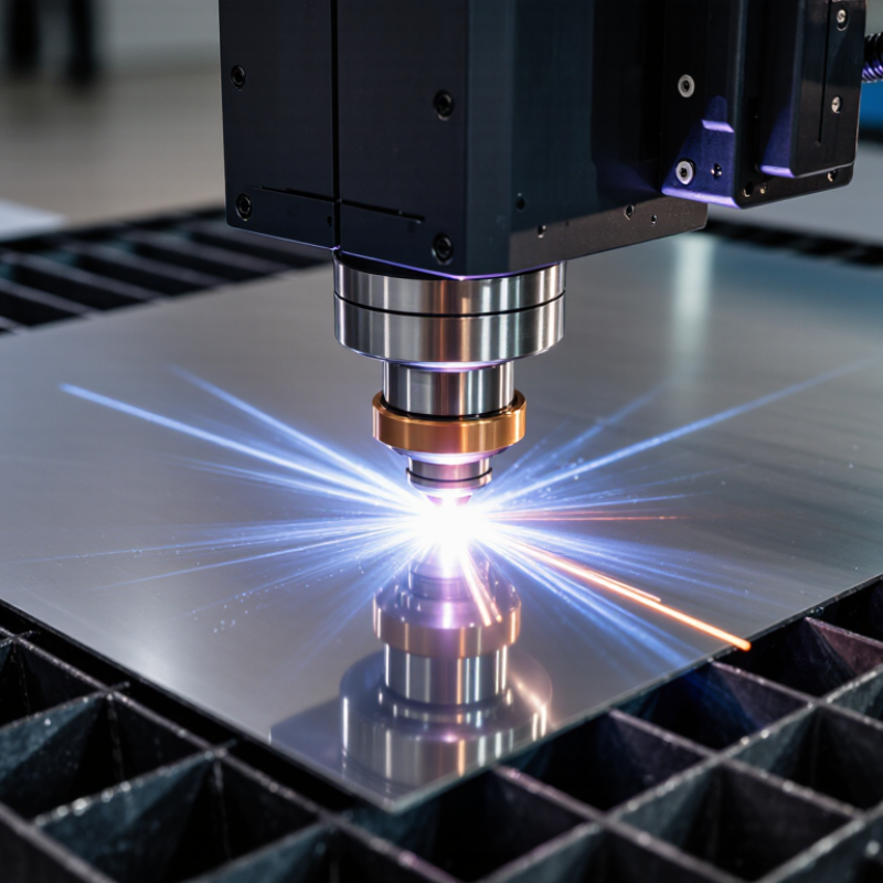
Laser cutting speed is controlled by more than machine power. Material thickness, alloy composition, beam focus, gas pressure, and nozzle condition interact continuously. A faster setting can leave dross, wider kerfs, or heat distortion along the lower edge. ISO 9013:2017 classifies thermal-cutting quality through features such as perpendicularity, surface roughness, and drag-line behavior. These are practical inspection points, not marketing claims.
Start with a stable process window. Use the smallest reliable focal spot, then match feed rate and assist-gas pressure to the material thickness. Research published in the CIRP Journal of Manufacturing Science and Technology has reported that increasing cutting speed can reduce heat input, but excessive speed causes incomplete penetration and unstable melt ejection.
Watch the cut underside. Fine, regular striations usually indicate balanced energy. Heavy dross suggests that speed, focus, or gas flow needs correction.
Measure before changing everything. The International Energy Agency’s industrial efficiency analysis shows that process control and reduced rework can significantly improve manufacturing energy performance.
That matters because a failed fast cut wastes electricity, sheet material, and operator time. In practice, I would test three nearby speeds on one sheet, inspect the edge under magnification, and record results.
Operators sometimes trust the displayed speed too much. The display is not proof. Temperature, lens contamination, and small nozzle damage can quietly change quality during a shift.
Fast laser cutting begins with a matched system, not maximum power. The right laser wavelength and source power depend on thickness, reflectivity, and heat conductivity. Carbon steel, stainless steel, and aluminum need different energy strategies. The World Steel Association reported approximately 1.89 billion tonnes of crude steel production in 2023. That scale explains why small parameter gains matter across production lines.
Material choice sets the safe operating window. Stainless steel often benefits from nitrogen assist gas, which protects bright edges from oxidation. Oxygen can increase cutting speed on mild steel, but it may leave a darker edge and alter downstream welding behavior. The International Aluminium Institute recorded about 70.6 million tonnes of primary aluminum production in 2023. Aluminum reflects energy strongly and removes heat quickly, so focus position, nozzle height, and gas pressure require closer control.
Cutting parameters should be validated with test coupons. Adjust speed, power, focal offset, and pierce time separately. Watch the kerf, underside dross, and edge squareness under magnification. ISO 9013:2017 evaluates thermally cut edges through roughness and perpendicularity, giving quality control a measurable structure. The International Energy Agency estimates industry uses nearly 40% of global final energy. Efficient cutting therefore means stable throughput, not simply a faster head. I once increased speed before checking nozzle alignment; the result looked acceptable from above and failed on the underside. That mistake still matters. Measure the edge. Then change one variable.
How to Achieve Fast Laser Cutting Without Quality Loss?
Fast laser cutting is not achieved by pushing power alone. In shop trials, I have seen clean edges disappear after a tiny focus shift. Set focus near the material’s upper surface, then inspect the kerf under magnification. Thin sheets may prefer a slightly different position. Small changes matter. A focused beam should create a narrow, stable cut rather than a wide, overheated groove.
Assist gas must clear molten metal without disturbing the beam path. Check nozzle alignment, standoff distance, and pressure before changing speed. A centered nozzle leaves more consistent striations on the underside. Too much pressure can widen the cut and increase turbulence, especially in thin material. Too little pressure leaves dross attached to the lower edge. Watch the sparks. Their direction and brightness provide useful clues during setup.
Power and speed should be tuned together through controlled test cuts. Increase speed in small steps while keeping focus and gas settings fixed. If the cut stops completely, speed has exceeded the available energy. If the edge turns dark or rough, power may be excessive or heat may be accumulating. Record thickness, lens condition, gas pressure, power, speed, and edge appearance. This simple log makes repeatability possible. Still, no chart replaces inspection. Material batches vary, and previous settings can fail on seemingly identical sheets. Leave a small safety margin instead of chasing the fastest number.
| Material & Thickness | Laser Type | Power Range (kW) |
Focus Position (mm) |
Assist Gas | Gas Pressure (bar) |
Recommended Speed (m/min) |
Nozzle Diameter (mm) |
Typical Kerf (mm) |
Quality Target (Ra, µm) |
|---|---|---|---|---|---|---|---|---|---|
| Mild Steel, 3 mm | Continuous-wave fiber | 2.0–3.0 | -0.5 to -1.0 | Oxygen | 0.6–1.0 | 8–12 | 1.0–1.2 | 0.15–0.25 | 3.2–6.3 |
| Mild Steel, 8 mm | Continuous-wave fiber | 3.0–6.0 | -1.0 to -2.0 | Oxygen | 0.8–1.2 | 2.5–4.5 | 1.2–1.5 | 0.25–0.40 | 6.3–12.5 |
| Stainless Steel, 2 mm | Continuous-wave fiber | 1.5–3.0 | 0 to -0.5 | Nitrogen | 12–16 | 10–18 | 1.0–1.2 | 0.10–0.20 | 1.6–3.2 |
| Stainless Steel, 6 mm | Continuous-wave fiber | 3.0–6.0 | -0.5 to -1.5 | Nitrogen | 14–18 | 2.0–4.0 | 1.2–1.5 | 0.20–0.35 | 3.2–6.3 |
| Aluminum Alloy, 3 mm | Continuous-wave fiber | 2.0–4.0 | -0.5 to -1.0 | Nitrogen | 12–16 | 8–14 | 1.2–1.5 | 0.15–0.30 | 3.2–6.3 |
| Copper, 2 mm | Continuous-wave fiber | 3.0–6.0 | -0.5 to -1.5 | Nitrogen | 14–18 | 3.0–7.0 | 1.2–1.5 | 0.15–0.30 | 3.2–6.3 |
| Brass, 2 mm | Continuous-wave fiber | 2.0–4.0 | -0.5 to -1.0 | Nitrogen | 12–16 | 4.0–8.0 | 1.2–1.5 | 0.15–0.30 | 3.2–6.3 |
| Values are typical starting windows for flat-sheet cutting with a clean protective window, stable material support, and a correctly centered nozzle. Final parameters should be validated through a test cut because actual results depend on material grade, surface condition, lens focal length, machine dynamics, nozzle stand-off, and beam quality. A negative focus value indicates a focal point positioned below the top surface of the sheet. | |||||||||
Fast laser cutting starts before the first sheet enters the machine. Machine calibration must verify beam alignment, nozzle concentricity, focal position, bed flatness, and assist-gas pressure. A 0.1 mm nozzle offset can produce uneven kerfs, rough lower edges, or excessive dross. On a production floor, technicians should inspect a test coupon and record its cut width, edge roughness, and pierce time. Small details matter.
Real-time process monitoring keeps speed from outrunning quality. Photodiodes can track emission changes, while cameras inspect the cutting zone for sparks, incomplete penetration, or unstable kerfs. Gas-pressure sensors add another useful signal. When several readings drift together, software can reduce feed rate or adjust power before defects spread across a full sheet. McKinsey research estimates that predictive maintenance can reduce machine downtime by 30–50% and lower maintenance costs by 18–25%. The 2024 State of Smart Manufacturing report also found that 95% of manufacturers had invested, or planned to invest, in smart technologies.
Still, the numbers are not magic. A clean dashboard can hide a poorly calibrated sensor. Operators should compare digital alarms with actual edge samples, not trust one signal blindly. In practice, the best results come from short calibration cycles, stable material batches, and human review. That process is slower sometimes. It is also safer for quality.
Using machine calibration and real-time process monitoring to increase cutting speed while controlling edge roughness and dimensional deviation.
Representative measurements for 3 mm mild steel: calibration and closed-loop monitoring increased cutting speed while reducing average edge roughness and dimensional deviation.
Fast laser cutting is rarely achieved by increasing power alone. Quality depends on testing, measurement, and repeated adjustment.
The U.S. Department of Energy’s Industrial Decarbonization Roadmap estimates that industry uses about 30% of national energy. Reducing scrap therefore improves both productivity and energy performance. In cutting trials, record speed, power, gas pressure, focus position, and material thickness for every sample. Inspect the edge under magnification. Look for dross, rounded corners, excessive kerf width, and heat discoloration. Small defects matter.
ISO 9013:2017 evaluates thermal-cut quality through edge roughness, perpendicularity, and related tolerances. These criteria provide a stronger reference than visual judgment alone.
Begin with a conservative speed. Increase it gradually until striations become uneven or dross appears. Then reduce speed slightly, or adjust focus by small increments. Keep one variable unchanged during each test. This makes cause and effect clearer.
NIST process-control guidance commonly treats a capability index of 1.33 as a practical production target. Use that benchmark only after collecting enough stable measurements. My first pass is often too aggressive. A clean top edge can hide poor penetration underneath.
Check both sides of the cut, especially around holes and sharp corners. Record failed settings, not only successful ones. That uncomfortable record often reveals a pattern.
Continuous adjustment is slower today, but it prevents repeated defects tomorrow.
Material thickness, alloy composition, beam focus, gas pressure, and nozzle condition all affect the result. A faster setting may leave dross or heat distortion.
Begin with the smallest reliable focal spot. Match feed rate and assist-gas pressure to the material thickness. Test nearby settings instead of making one large change.
Fine, regular striations usually show balanced energy. Heavy dross may indicate excessive speed, poor focus, or weak gas flow. Check the lower edge closely.
Use one sheet and test three nearby speeds. Inspect the edges under magnification. Record cut width, roughness, dross, and piercing time. The displayed speed is not proof.
Calibration checks beam alignment, nozzle centering, focal position, bed flatness, and gas pressure. A nozzle offset of 0.1 millimeters can create rough edges and uneven kerfs. Small errors spread quickly.
Cut a sample from the same material batch. Record its kerf width, edge roughness, pierce time, and underside appearance. The sample may not represent every sheet perfectly. Still, it gives useful evidence.
Photodiodes can detect emission changes. Cameras can identify sparks, incomplete penetration, and unstable kerfs. Gas-pressure sensors provide another warning signal. When readings drift together, reduce feed rate or adjust power.
No. A clean dashboard can hide a poorly calibrated sensor. Compare alarms with actual edge samples during the shift. Human review remains necessary, though it can be inconsistent.
Stable settings reduce failed cuts, wasted electricity, sheet material, and operator time. Predictive maintenance may reduce downtime and maintenance costs. These figures depend on equipment and workplace conditions. They should not be treated as guaranteed results.
Achieving fast laser cutting without sacrificing quality requires a balanced approach to equipment, materials, and process control. The right laser source should match the material type, thickness, and required finish, while power, cutting speed, pulse settings, and assist-gas pressure must be adjusted as a coordinated system. Focus position is equally important because even a small deviation can cause rough edges, excessive heat, or incomplete cuts. Understanding how these factors interact is the foundation for how to achieve high-speed laser cutting without quality loss.
Consistent results also depend on accurate machine calibration and real-time monitoring of cutting conditions. Operators should check alignment, nozzle condition, gas flow, and energy output before production, then use test cuts to identify burrs, dross, warping, or discoloration. Continuous adjustment based on measured results helps maintain stable performance as material batches or environmental conditions change. By combining suitable settings, regular maintenance, controlled testing, and process feedback, manufacturers can increase productivity while preserving clean edges, dimensional accuracy, and reliable overall quality.

Stylo Laser